
Digital Communication Standard -
Ademco ® Contact ID Protocol -
for Alarm System
Communications
SIA DC-05-1999.09
Sponsor
Security Industry Association
Copyright 1999 - Ademco Group
Publication Order Number: 14085


Digital Communication Standard - Ademco ® Contact ID Protocol - for Alarm System Communications
FOREWORD
This standard documents a communications protocol that was developed and is wholly owned by ADEMCO Group,
a division of Pittway Corporation . It is published by the Security Industry Association (SIA) as a de facto security
industry standard. It is intended to facilitate product compatibility and interchangeability, to reduce
misunderstandings between manufacturers and purchasers, and to assist purchasers in obtaining the proper products
to fulfill their particular needs.
The existence of this or any SIA standards document shall not prevent any SIA member or non-member from
manufacturing, selling, or using products not conforming to this or any SIA standard. SIA standards are voluntary.
SIA encourages the use of this document but will not take any action to ensure compliance with this or any other
SIA Standard.
Neither SIA nor Ademco assume any responsibility for the use, application or misapplication of this protocol.
Although some SIA standards establish minimum performance requirements, they are intended neither to preclude
additional product features or functions nor to act as a maximum performance limit. Any product, the specifications
of which meet the minimum requirements of a SIA standard, shall be considered in compliance with that standard.
Any product, the specifications of which exceed the minimum requirements of a SIA standard, shall also be
considered in compliance with the standard, provided that such product specifications do not exceed any maximum
requirements set by the standard. SIA standards are not intended to supersede any recommended procedures set by a
manufacturer for its products.
Ademco reserves the right to revise this protocol at any time. Users of this document are cautioned to obtain and
use the most recent edition of this standard. Current information regarding the revision level or status of this or any
other SIA standard may be obtained by contacting SIA.
Requests to modify this document are welcome at any time from any party, regardless of membership affiliation
with SIA. Such requests are to be made in writing, clearly identifying this document and the text within it related to
the proposed modification, and include a draft of the proposed changes with supporting comments. Requests for
new Event Codes are to include a description of the event to be reported as well as a short justification. Submission
of requests are to be accompanied by the name, phone number, and e-mail address (if available) of the person
making the request. Requests are to be sent directly to Ademco, preferably by email, care of:
Rich Hinkson: Rich_Hinkson@ademco.com
or
Bob Orlando: Bob_Orlando@ademco.com
Decisions to modify this protocol are at the sole discretion of Ademco, and Ademco reserves the right to deny
requests. When a decision is made regarding a request for modification, Ademco will notify the requestor.
Whenever a modification is made to this protocol, Ademco will inform SIA so that SIA may update this document
and notify other interested parties. Ademco may, at its discretion, also maintain a current list of Event Codes for this
protocol on its web site: http://www.ademco.com
Written requests for interpretations of this standard and other matters of document publication should be addressed
to:
Standards
Security Industry Association
635 Slaters Lane, Suite 110
Alexandria, VA 22314
E-mail: Standards@siaonline.com
Internet: http://www.siaonline.org
SIA DC-05-1999.09
ADEMCO Group
Page i

Digital Communication Standard - Ademco ® Contact ID Protocol - for Alarm System Communications
ACKNOWLEDGMENTS
This document was developed by Richard Hinkson of the ADEMCO Group, a division of Pittway
Corporation .
The Ademco “Contact ID” protocol has become a prevalent and respected format for digital
communications between security alarm systems and central monitoring stations. Many manufacturers
have adopted it, seeking industry wide compatibility.
SIA gratefully acknowledges Ademco’s generous contribution to communications in the security
industry, both in allowing SIA to publish this protocol as a de facto security industry standard and in
accepting industry requests for modifications.
SIA DC-05-1999.09
ADEMCO Group
Page ii

Digital Communication Standard - Ademco ® Contact ID Protocol - for Alarm System Communications
REVISION HISTORY
The following are changes made to this document, listed by revision.
SEPTEMBER 1999 BASELINE
Original Publication
SIA DC-05-1999.09
ADEMCO Group
Page iii

Digital Communication Standard - Ademco ® Contact ID Protocol - for Alarm System Communications
This page intentionally blank.
SIA DC-05-1999.09
ADEMCO Group
Page iv

Digital Communication Standard - Ademco ® Contact ID Protocol - for Alarm System Communications
Table of Contents
1.
SCOPE....................................................................................................................................1
1.1 Objectives............................................................................................................................1
2.
CONVENTIONS AND DEFINITIONS.................................................................................1
2.1 Conventions.........................................................................................................................1
2.1.1 Units of Measurement. ................................................................................................1
2.1.2 Tolerances ...................................................................................................................1
2.1.3 Special Capitalization..................................................................................................1
2.1.4 Nomenclature and Identification of Sections..............................................................2
2.1.5 Binding Language .......................................................................................................2
2.2 Definitions ...........................................................................................................................2
3.
REFERENCE DOCUMENTS ................................................................................................4
4.
TRANSMISSION REQUIREMENTS ...................................................................................4
4.1 Transmission Components ..................................................................................................4
4.1.1 Handshake Tones ........................................................................................................4
4.1.2 Message Blocks...........................................................................................................5
4.1.2.4 Inter-Message Time....................................................................................................6
4.1.3 Kissoff (Acknowledgement) Tone..............................................................................6
4.1.4 Maximum Number of Attempts ..................................................................................6
APPENDIX A: EXAMPLE MESSAGES ....................................................................................7
Example 1 – Alarm Message ......................................................................................................7
Example 2 – Restoral Message ...................................................................................................7
Example 3 – Opening Message ...................................................................................................8
APPENDIX B: MESSAGE TRANSMISSION FLOWCHART..................................................9
APPENDIX C: EVENT CODES ................................................................................................10
SIA DC-05-1999.09
ADEMCO Group
Page v


Digital Communication Standard - Ademco ® Contact ID Protocol - for Alarm System Communications
Digital Communication Standard -
Ademco ® Contact ID Protocol -
for Alarm System Communications
time the line is seized and not
1. SCOPE
available to the customer.
c) Minimize the transmission error rate
This standard details the specification for the
“Ademco ® Contact ID” communication
d) Minimize the cost of the hardware
associated with the transmission of the
format, originally developed by the Ademco
information
Group, a division of Pittway Corporation.
The purpose of this standard is to detail the
Contact ID signaling format such that it can
2. CONVENTIONS AND
be adopted by any manufacturer of digital
DEFINITIONS
transmitters or receivers. Documentation
and distribution of this communication
format is intended to provide an across-the-
board compatibility of equipment designed
2.1 Conventions
to this standard regardless of manufacturer.
2.1.1 Units of Measurement.
This communications format utilizes
In accordance with SIA Policy, the units of
standard DTMF tones for transmission of
measurements used throughout this
the information.
publication are the units of the System
International d’ Unites (SI), commonly
known as metric units. Equivalent English
1.1 Objectives
Units, enclosed in parenthesis, are also used
in this publication. These equivalent
a) Provide information regarding events
English Units are approximate conversions
that are occurring on a customer’s
and are provided for easy reference.
premises. This information should be
in a form that can easily be interpreted
2.1.2 Tolerances
by a central station operator.
Unless otherwise specified, the tolerance for
measurements specified within this standard
b) Spend minimum practical time on line
shall be 10 percent (±10%).
per transaction, to minimize the
number of receivers required to
2.1.3 Special Capitalization.
handle the traffic and minimize the
SIA DC-05-1999.09
ADEMCO Group
Page 1

Digital Communication Standard - Ademco ® Contact ID Protocol - for Alarm System Communications
Alarm sequence events, alarm system
Acknowledgment , or ACK, or Positive
commands and states, and digital
Acknowledgment - A signal sent from one
communication codes transmitted by the
participant in the communication process to
control panel to the central station are
the other indicating that the data has been
capitalized within the text of this standard.
correctly received.
Alarm - An indication of an emergency
2.1.4 Nomenclature and
condition. The condition may be that of an
Identification of Sections.
intrusion, a fire, a medical panic, etc.
Sections within this standard are identified
Locally the condition usually causes visual
and referenced by the number preceding
and/or audible annunciation. In a system
each section. Unless otherwise specified,
that is monitored, this condition is
references to a section refer to only that
transmitted to remote equipment.
section and not to subsequent subsections
within the section.
Alarm Panel - see Control.
Alarm Cancel , or Manual Reset - An action
2.1.5 Binding Language
restoring the alarm panel to a non-alarm
This standard uses the term “shall” to
state. Also the transmission of that change
convey binding requirements.
indicating that the previous alarm signal is
to be disregarded.
The term “may” is used to convey features
Alarm Verification – Generic name given
that are allowed but not required.
to many techniques used to confirm or deny
Terms such as “is”, “are”, “will”, and others
the validity of alarms signals received at the
monitoring facility. (Also see Verified
are used to convey statements of fact for
advisory purposes only.
Alarm)
Arm - To turn on a security system.
The annotation “Note:” also precedes
Area - A defined section of the protected
advisory information
system that can be armed and disarmed
independently. This is sometimes also
2.2 Definitions
referred to as a partition . When areas are
used, they are numbered consecutively
For the purpose of this standard, the
beginning with 1.
following terms have the meaning indicated.
Bypass - To cause a system to ignore input
changes from a given point or zone,
Abort - A manual intervention during a
regardless of the arming state. Bypassed
process that prevents completion of that
points and zones do not cause alarm events.
process.
(Also see Zone Bypass, Unbypass)
Access Code , or Code - A series of digits
Close, or Closing - The manual or automatic
that a user enters on a keypad to access the
arming of a security system. (Also see Early
system for arming or disarming.
to Close, Fail to Close, Late to Close)
Account , or Account Number - Information
Code - see Access Code, User Code
that identifies a particular alarm panel.
Control , Control Panel, or Alarm Panel -
ACK , see Acknowledgment.
The part of a security system that handles
SIA DC-05-1999.09
ADEMCO Group
Page 2

Digital Communication Standard - Ademco ® Contact ID Protocol - for Alarm System Communications
control and communication, whether as
operation, or otherwise interact with the
combined or separate physical units.
system.
Disarm - To turn off a security system
Late to Close , or LTC - An event created by
(except for 24 hr devices).
the arming of a system after a specified
DTMF or D ual T one M ulti- F requency – A
time.
standard signaling method for dialing and
Late to Open , or LTO - An event created by
data transmission using a combination of
the disarming of a system after a specified
two sine waves at different frequencies. It is
time.
commonly referred to as Touch-Tone®
Open, or Opening - The manual or
signaling.
automatic disarming of a security system
Duress - A code that can be entered if one
(see also Early to Open, Fail to Open, Late
or more persons try to force an individual to
to Open)
enter, or re-enter, a facility against the
Panic - A general type of perceived
individual’s will.
emergency, including the presence of one or
Early to Close , or ETC - An event created
more unwanted persons trying to gain entry
by the arming of a system before a specified
or observed intruders on the private grounds.
time.
Partition - see Area.
Early to Open , or ETO - An event created
Point – an electronically addressable sensor,
by the disarming of a system before a
sometimes used interchangeably with the
specified time.
term sensor . The term is usually used in
Entry Delay or Entry Time - The period of
multiplex alarm systems or for RF (wireless)
time allowed, after entry to the premises, to
sensors.
disarm the security system before tripping
Receiver - The equipment located at the
an alarm.
central station that communicates with a
Exit Error – A signal produced by a point
control panel.
or zone that is still violated when the exit
Recent Closing - A transmission indicating
time has expired.
that the security system has recently been
Exit Delay , or Exit Time - The period of
armed.
time allowed, after arming a security system,
Report - An electronic transmission sent by
to exit the premises before tripping an alarm.
the control panel to the central station
Fail to Close, or FTC - An event created by
containing detailed information about an
the system at a preset time if it remains in
event detected by or a status of the security
the disarmed state.
system.
Fail to Open , or FTO - An event created by
the system at a preset time if it remains in
Sounder - An audible annunciator
the armed state.
producing sufficient volume to be heard by
person(s) within the protected premises.
Handshake - A signal sent by one end of
the communication channel to the other
Subscriber - see User.
indicating reception of signal.
Supervisory Signal - A signal indicating the
Keypad - The part(s) of a security system
need of action in connection with the
from which a human operator can arm and
supervision of guard tours, fire suppression
disarm the system, manipulate the system
systems or equipment, or with the
SIA DC-05-1999.09
ADEMCO Group
Page 3

Digital Communication Standard - Ademco ® Contact ID Protocol - for Alarm System Communications
maintenance features of related systems.
should be obtained from the manufacturer of
(Not to be confused with a Trouble signal
that product.
generated from a supervised zone or point.)
Transmitter - The part of the security
Other unrelated standards for digital
system that sends electronic data outside the
communications may be obtained from the
system, typically to a central station. (Also
Security Industry Association.
see Control Panel.)
Trip - An alarm state produced as a result of
detection by a sensor.
4. TRANSMISSION
REQUIREMENTS
Trouble – A signal sent to indicate a
malfunction, miss-operation, or loss of
contact with a supervised zone or point.
This section describes the basic components
Unbypass - To restore a point or zone to
of a communication session.
normal functioning by removing a bypass
condition.
4.1 Transmission Components
User - The person(s) at the alarm panel site
that operate and/or have access to the
The transmitter to receiver communication
system.
session is composed of three basic elements:
the Handshake Tone sequence , Message
User Code - see Access Code.
Blocks , and Acknowledgements .
Verified Alarm – An alarm that has been
confirmed by monitoring facility contact
The Handshake Tone sequence consists of a
with the protected premises or an authorized
pair of single-frequency tones sequenced in
user agent, an alarm from sequentially
time.
detected and reported events, a multiple-
sensor detected event, or an alarm reported
The Message Blocks consist of a series of
by a system user. (Also see Alarm
DTMF tone bursts separated by spaces.
Verification.)
The Acknowledgement Tone is a single tone
Zone - A dedicated input to the control
burst.
panel containing one or more sensor devices
that will trip the input upon activation of any
one-sensor device.
4.1.1 Handshake Tones
The Handshake Tone sequence is produced
Zone Bypass - see Bypass
by the RECEIVER. The purpose is to signal
the TRANSMITTER that the
communication channel is ready.
3. REFERENCE DOCUMENTS
4.1.1.1 Placement
The Handshake Tone sequence is emitted by
This de facto standard does not rely on any
the receiver after going off-hook and
other documents for implementation.
delaying an interval of at least 0.5 seconds
but typically no greater than 2.0 seconds.
Information regarding a specific product that
This time allows the phone network
has implemented this de facto standard
SIA DC-05-1999.09
ADEMCO Group
Page 4

Digital Communication Standard - Ademco ® Contact ID Protocol - for Alarm System Communications
connection to settle before the
18 or a 98. Note that some older
communication process begins.
receivers may not accept 98 .
4.1.1.2 Composition
Q = Event qualifier, which gives specific
The handshake tone sequence shall consist
event information:
of:
1 = New Event or Opening
duration of 100 msec. ±5%
3 = New Restore or Closing
6 = Previously reported condition still
present (Status report)
duration of 100 msec. ±5%
XYZ = Event code (3 Hex digits 0-9,B-F)
Note: Transmitters shall accept a
frequency error of at least ± 5% to ensure
GG = Group or Partition number (2 Hex
back-compatibility with older receivers.
digits 0-9, B-F). Use 00 to indicate
that no specific group or partition
4.1.2 Message Blocks
information applies.
A Message Block is sent by the
TRANSMITTER for each message in the
CCC = Zone number (Event reports) or User
transmitter’s message queue. Each message
# (Open / Close reports ) (3 Hex
block contains sufficient information to
digits 0-9,B-F ). Use 000 to indicate
report an event in the system.
that no specific zone or user
information applies
4.1.2.1 Placement
The first message block is sent beginning
S = 1 Digit Hex checksum calculated such
250 msec. (250 min.,300 max.) after the end
that:
of either the Handshake Tone sequence or
after a Kissoff (Acknowledgement) tone.
(Sum of all message digits + S) MOD 15 = 0
The delay is timed from the end of the tone.
Note: A ‘0’ shall be transmitted as a 10 and
4.1.2.2 Message Composition
valued as a 10 for checksum purposes even
though it is displayed and printed as ‘0’. It
The form of the message is:
uses the same tone pair as the ‘0’ (OPER)
key on a standard telephone.
ACCT MT QXYZ GG CCC
4.1.2.3 Data Tones
where:
The message is sent using standard DTMF
ACCT = 4 Digit Account number (0-9, B-F)
tones.
MT = Message Type. This 2-digit sequence
The timing of the tones shall be as follows:
is used to identify the Contact ID
message to the receiver. It may be
Burst ON time - 50 msec. (50 min.,60 max.)
transmitted as either 18 (preferred) or
Burst OFF time- 50 msec. (50 min.,60 max.)
98 (optional). New receiver
implementations shall accept either a
The details of the tones are contained in the
following table.
SIA DC-05-1999.09
ADEMCO Group
Page 5

Digital Communication Standard - Ademco ® Contact ID Protocol - for Alarm System Communications
Kissoff Tone from the receiver. If the start
Data Transmission Frequencies -
of a kissoff tone is detected, the transmitter
Standard DTMF Signaling
must continue timing the tone, even if the
inter-message time expires. The panel must
Digit
Low
High
Digit
detect a minimum of 400 msec. of the
Tone
Tone
Value
Kissoff Tone for it to be considered to be
(Hz.)
(Hz. )
valid.
If a Kissoff tone is detected, the transmitter
0
941
1336
10
should wait for the tone to end and then wait
1
697
1209
1
250 msec. (250 min.,300 max.) before
beginning the next message.
2
697
1336
2
If no Kissoff Tone is received, the
3
697
1477
3
transmitter should repeat the message after
4
770
1209
4
the expiration of the 1.25 second inter-
5
770
1336
5
message interval.
6
770
1477
6
4.1.3 Kissoff (Acknowledgement)
7
852
1209
7
Tone
8
852
1336
8
The Kissoff tone from the receiver is used to
9
852
1477
9
tell the transmitter that the message has been
received successfully. The frequency of the
B (*)
941
1209
11
tone shall be 1400 Hz. ±3% and shall be sent
C (#)
941
1477
12
by the receiver for a minimum of 750 msec.
D
697
1633
13
and a maximum period of 1 second.
E
770
1633
14
The transmitter must detect a minimum of
400 msec. of tone before considering the
F
852
1633
15
kissoff to be valid.
Notes:
Note: Transmitters shall accept a frequency
error of at least ± 5% to ensure back-
1) The digit ‘0’ is transmitted with a value
compatibility with older receivers
of 10 and shall be counted as a 10 in the
calculation of the message checksum.
4.1.4 Maximum Number of Attempts
The transmitter shall make up to 4 attempts
2) The DTMF pair of 941 Hz. And 1633
to deliver a message before hanging up and
Hz. is not used in this format and shall
redialing. The attempts counter is reset each
not be sent.
time a valid kissoff signal is received.
3) The frequency deviation on each of the
above frequencies shall be ± 1.5% max.
4.2 Data Codes
4.1.2.4 Inter-Message Time
The data codes used to transmit events are
After sending its message, the transmitter
contained in Appendix C: Event Codes.
should wait for 1.25 sec. for the start of a
SIA DC-05-1999.09
ADEMCO Group
Page 6

Digital Communication Standard - Ademco ® Contact ID Protocol - for Alarm System Communications
APPENDIX A: EXAMPLE MESSAGES
Example 1 – Alarm Message
Example 2 – Restoral Message
Account 1234 is reporting a Perimeter
Account 1234 is reporting a Restore of a
Burglary Alarm on Zone 15 of Partition 1
Perimeter Burglary Alarm on Zone 15 of
Partition 1
The message shall be sent as:
The message shall be sent as:
1234 18 1131 01 015 8
1234 18 3131 01 015 6
where:
where:
1234 = The account number (1234)
18
= The message type used to identify
1234 = The account number (1234)
the message as Contact ID
18
= The message type used to identify
1131 = The Event Qualifier (1) for a new
the message as Contact ID
event, followed by the Event
3131 = The Event Qualifier (3) for a
Code for Perimeter Burglary
restoral, followed by the Event
(131)
Code for Perimeter Burglary
01
= The partition number (1)
(131)
015
= The zone number (015)
01
= The partition number (1)
8
= The checksum, computed in the
015
= The zone number (015)
following manner:
6
= The checksum (See Example 1)
a) Add all of the message digits
together, using 10 for all ‘0’ digits
(1+2+3+4)+(1+8)+(1+1+3+1)+(1
0+1)+(10+1+5) = 52
b) Find the next highest multiple of
15, in this case 60.
c) Subtract the sum from this value
(60-52 = 8)
d) Use the result for the checksum..
If the result is 0, use the digit ‘F’
(15) for the checksum.
SIA DC-05-1999.09
ADEMCO Group
Page 7

Digital Communication Standard - Ademco ® Contact ID Protocol - for Alarm System Communications
Example 3 – Opening Message
Example 4 – Closing Message
User 3 disarms Partition 2 of Account 1234
User 5 arms Partition 3 of Account 1234
The message shall be sent as:
The message shall be sent as:
1234 18 1401 02 003 5
1234 18 3401 03 005 F
where
where
1234 = The account number (1234)
1234 = The account number (1234)
18
= The message type used to identify
18
= The message type used to identify
the message as Contact ID
the message as Contact ID
1401 = The Event Qualifier (1) for an
3401 = The Event Qualifier (3) for a
Opening, followed by the Event
Closing, followed by the Event
Code for Open/Close by User
Code for Open/Close by User
(401)
(401)
02
= The partition number (2)
03
= The partition number (2)
003
= The User number (003)
005
= The User number (003)
5
= The checksum (See Example 1)
F
= The checksum (See Example 1)
Note the use of ‘F’ since the sum of the
message digits is an even multiple of 15.
SIA DC-05-1999.09
ADEMCO Group
Page 8
Digital Communication Standard - Ademco ® Contact ID Protocol - for Alarm System Communications
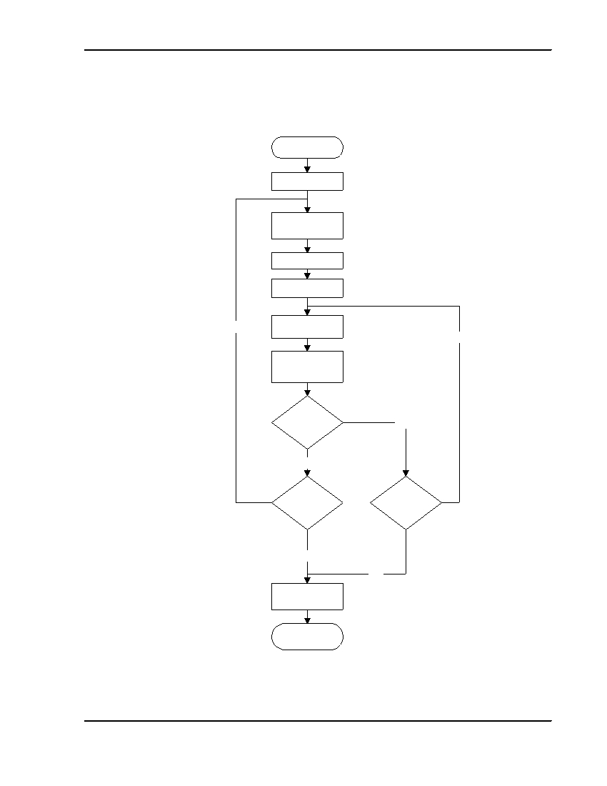
APPENDIX B: MESSAGE TRANSMISSION FLOWCHART
Send Message
Detect Handshake
Wait for end of
tone(s)
Delay 250 msec.
Format message
Attempt count = 1
Yes
Transmit message
No
Search for Kissoff
tone
Kissoff
No
received?
Yes
More
Increment
attempt count
messages ?
Count > 4?
No
Yes
Hang up
End
SIA DC-05-1999.09
ADEMCO Group
Page 9
Digital Communication Standard - Ademco ® Contact ID Protocol - for Alarm System Communications
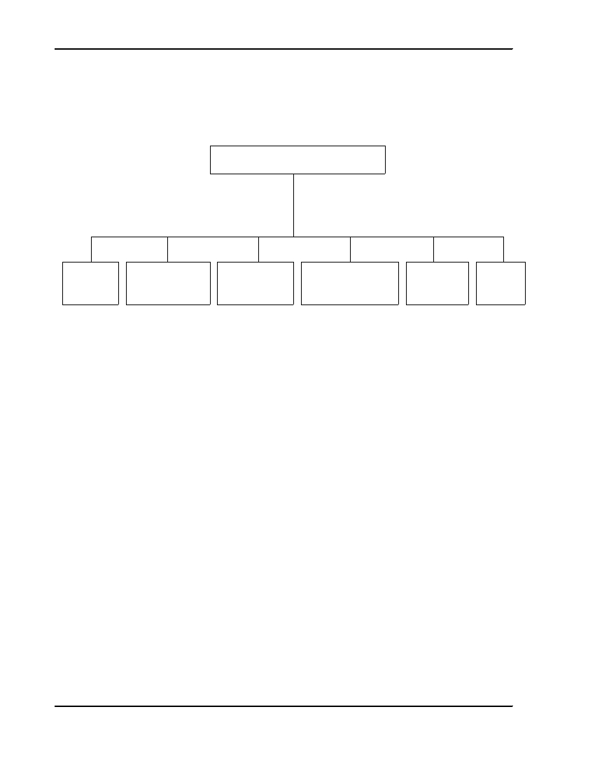
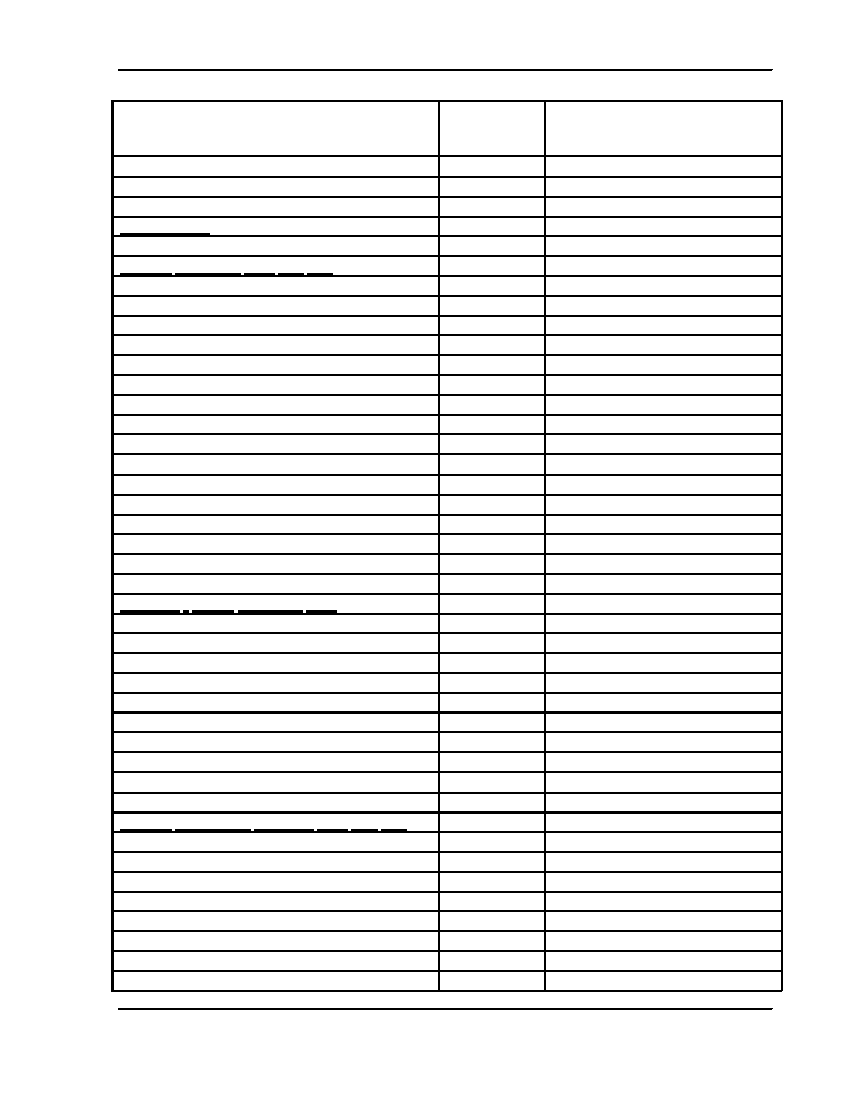
APPENDIX C: EVENT CODES
EVENT CODE CLASSIFICATIONS
100
200
300
400
500
600
ALARMS
SUPERVISORY
TROUBLES
OPEN/CLOSE
BYPASSES/
TEST/
REMOTE ACCESS
DISABLES
MISC
Medical
Fire
System
Open/Close
System
Test
Fire
Sounder/Relay
Remote Access
Sounder/Rly
Log
Panic
Sys. Per.
Access Control
Sys. Per.
Sched.
Burglary
Comm.
Comm.
General
Prot. Loop
24 Hour
Sensor
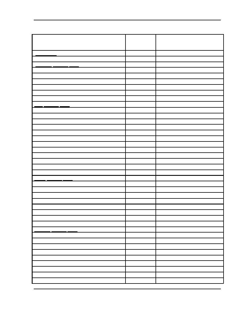
Notes on Event Code definitions
1) The following table defines the Event Codes used in this protocol.
2) The Data Type identifies the information sent in the CCC field as either Zone number or
User number.
3) The value in the CCC field should be set to 000 if no useful information is being sent.
4) Descriptions for the Event Codes will be added in a later revision of this standard.
SIA DC-05-1999.09
ADEMCO Group
Page 10
Digital Communication Standard - Ademco ® Contact ID Protocol - for Alarm System Communications
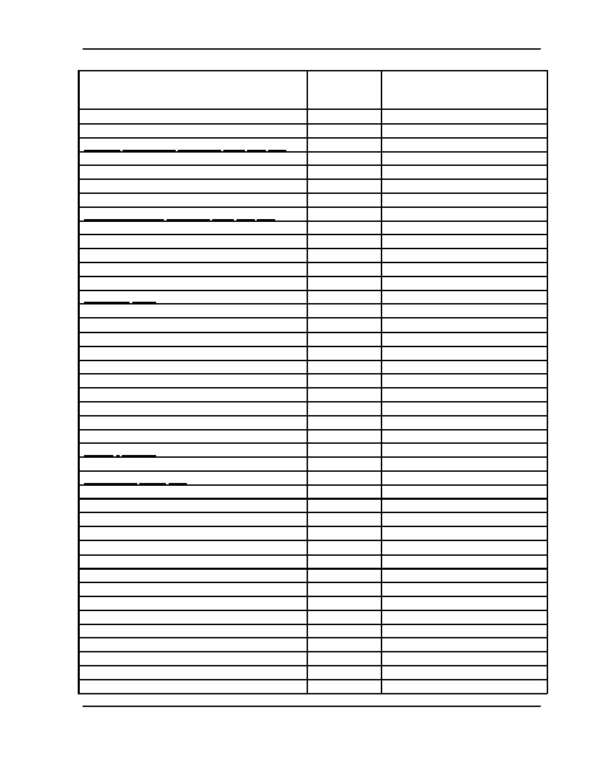
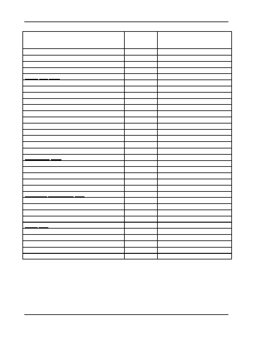
Event
Data Type Description (to be supplied in a
later revision of this standard)
ALARMS
Medical Alarms –100
100 Medical
Zone
101 Personal Emergency
Zone
102 Fail to report in
Zone
Fire Alarms –110
110 Fire
Zone
111 Smoke
Zone
112 Combustion
Zone
113 Water flow
Zone
114 Heat
Zone
115 Pull Station
Zone
116 Duct
Zone
117 Flame
Zone
118 Near Alarm
Zone
Panic Alarms –120
120 Panic
Zone
121 Duress
User
122 Silent
Zone
123 Audible
Zone
124 Duress – Access granted
Zone
125 Duress – Egress granted
Zone
Burglar Alarms –130
130 Burglary
Zone
131 Perimeter
Zone
132 Interior
Zone
133 24 Hour (Safe)
Zone
134 Entry/Exit
Zone
135 Day/night
Zone
136 Outdoor
Zone
137 Tamper
Zone
SIA DC-05-1999.09
ADEMCO Group
Page 11
Digital Communication Standard - Ademco ® Contact ID Protocol - for Alarm System Communications
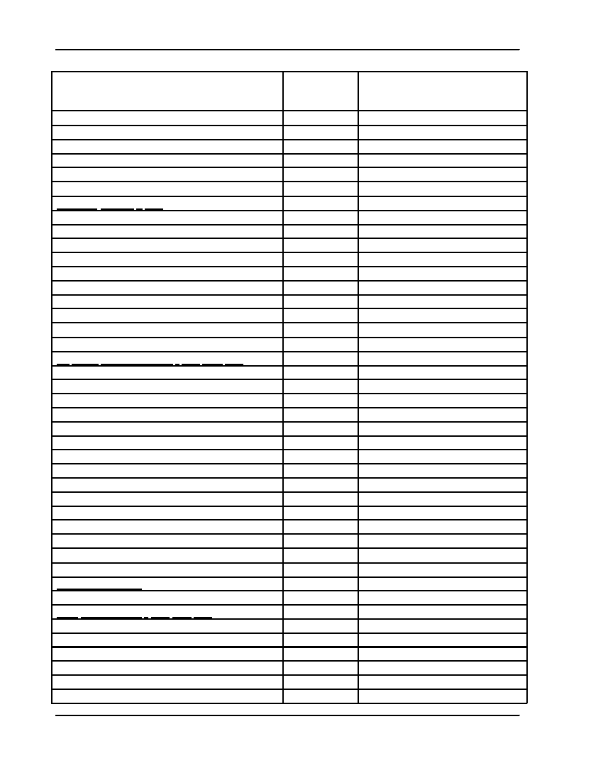
Event
Data Type Description (to be supplied in a
later revision of this standard)
138 Near alarm
Zone
139 Intrusion Verifier
Zone
General Alarm – 140
140 General Alarm
Zone
141 Polling loop open
Zone
142 Polling loop short
Zone
143 Expansion module failure
Zone
144 Sensor tamper
Zone
145 Expansion module tamper
Zone
146 Silent Burglary
Zone
147 Sensor Supervision Failure
Zone
24 Hour Non-Burglary - 150 and 160
150 24 Hour Non-Burglary
Zone
151 Gas detected
Zone
152 Refrigeration
Zone
153 Loss of heat
Zone
154 Water Leakage
Zone
155 Foil Break
Zone
156 Day Trouble
Zone
157 Low bottled gas level
Zone
158 High temp
Zone
159 Low temp
Zone
161 Loss of air flow
Zone
162 Carbon Monoxide detected
Zone
163 Tank level
Zone
SUPERVISORY
Fire Supervisory - 200 and 210
200 Fire Supervisory
Zone
201 Low water pressure
Zone
202 Low CO2
Zone
203 Gate valve sensor
Zone
204 Low water level
Zone
SIA DC-05-1999.09
ADEMCO Group
Page 12
Digital Communication Standard - Ademco ® Contact ID Protocol - for Alarm System Communications
Event
Data Type Description (to be supplied in a
later revision of this standard)
205 Pump activated
Zone
206 Pump failure
Zone
TROUBLES
System Troubles -300 and 310
300 System Trouble
Zone
301 AC Loss
Zone
302 Low system battery
Zone
303 RAM Checksum bad
Zone
304 ROM checksum bad
Zone
305 System reset
Zone
306 Panel programming changed
Zone
307 Self-test failure
Zone
308 System shutdown
Zone
309 Battery test failure
Zone
310 Ground fault
Zone
311 Battery Missing/Dead
Zone
312 Power Supply Overcurrent
Zone
313 Engineer Reset
User
Sounder / Relay Troubles -320
320 Sounder/Relay
Zone
321 Bell 1
Zone
322 Bell 2
Zone
323 Alarm relay
Zone
324 Trouble relay
Zone
325 Reversing relay
Zone
326 Notification Appliance Ckt. # 3
Zone
327 Notification Appliance Ckt. #4
Zone
System Peripheral Trouble -330 and 340
330 System Peripheral trouble
Zone
331 Polling loop open
Zone
332 Polling loop short
Zone
333 Expansion module failure
Zone
334 Repeater failure
Zone
335 Local printer out of paper
Zone
336 Local printer failure
Zone
SIA DC-05-1999.09
ADEMCO Group
Page 13

Digital Communication Standard - Ademco ® Contact ID Protocol - for Alarm System Communications
Event
Data Type Description (to be supplied in a
later revision of this standard)
337 Exp. Module DC Loss
Zone
338 Exp. Module Low Batt.
Zone
339 Exp. Module Reset
Zone
341 Exp. Module Tamper
Zone
342 Exp. Module AC Loss
Zone
343 Exp. Module self-test fail
Zone
344 RF Receiver Jam Detect
Zone
Communication Troubles -350 and 360
350 Communication trouble
Zone
351 Telco 1 fault
Zone
352 Telco 2 fault
Zone
353 Long Range Radio xmitter fault
Zone
354 Failure to communicate event
Zone
355 Loss of Radio supervision
Zone
356 Loss of central polling
Zone
357 Long Range Radio VSWR problem
Zone
Protection Loop -370
370 Protection loop
Zone
371 Protection loop open
Zone
372 Protection loop short
Zone
373 Fire trouble
Zone
374 Exit error alarm (zone)
Zone
375 Panic zone trouble
Zone
376 Hold-up zone trouble
Zone
377 Swinger Trouble
Zone
378 Cross-zone Trouble
Zone
Sensor Trouble -380
380 Sensor trouble
Zone
381 Loss of supervision - RF
Zone
382 Loss of supervision - RPM
Zone
383 Sensor tamper
Zone
384 RF low battery
Zone
385 Smoke detector Hi sensitivity
Zone
386 Smoke detector Low sensitivity
Zone
387 Intrusion detector Hi sensitivity
Zone
388 Intrusion detector Low sensitivity
Zone
SIA DC-05-1999.09
ADEMCO Group
Page 14

Digital Communication Standard - Ademco ® Contact ID Protocol - for Alarm System Communications
Event
Data Type Description (to be supplied in a
later revision of this standard)
389 Sensor self-test failure
Zone
391 Sensor Watch trouble
Zone
392 Drift Compensation Error
Zone
393 Maintenance Alert
Zone
OPEN/CLOSE/REMOTE ACCESS
Open/Close -400, 440,450
400 Open/Close
User
401 O/C by user
User
402 Group O/C
User
403 Automatic O/C
User
404 Late to O/C (Note: use 453, 454 instead ) User
405 Deferred O/C (Obsolete- do not use )
User
406 Cancel
User
407 Remote arm/disarm
User
408 Quick arm
User
409 Keyswitch O/C
User
441 Armed STAY
User
442 Keyswitch Armed STAY
User
450 Exception O/C
User
451 Early O/C
User
452 Late O/C
User
453 Failed to Open
User
454 Failed to Close
User
455 Auto-arm Failed
User
456 Partial Arm
User
457 Exit Error (user)
User
458 User on Premises
User
459 Recent Close
User
461 Wrong Code Entry
Zone
462 Legal Code Entry
User
463 Re-arm after Alarm
User
464 Auto-arm Time Extended
User
465 Panic Alarm Reset
Zone
466 Service On/Off Premises
User
SIA DC-05-1999.09
ADEMCO Group
Page 15

Digital Communication Standard - Ademco ® Contact ID Protocol - for Alarm System Communications
Event
Data Type Description (to be supplied in a
later revision of this standard)
Remote Access –410
411 Callback request made
User
412 Successful download/access
User
413 Unsuccessful access
User
414 System shutdown command received
User
415 Dialer shutdown command received
User
416 Successful Upload
Zone
Access control –420,430
421 Access denied
User
422 Access report by user
User
423 Forced Access
Zone
424 Egress Denied
User
425 Egress Granted
User
426 Access Door propped open
Zone
427 Access point Door Status Monitor trouble
Zone
428 Access point Request To Exit trouble
Zone
429 Access program mode entry
User
430 Access program mode exit
User
431 Access threat level change
User
432 Access relay/trigger fail
Zone
433 Access RTE shunt
Zone
434 Access DSM shunt
Zone
BYPASSES / DISABLES
System Disables -500 and 510
501 Access reader disable
Zone
Sounder / Relay Disables -520
520 Sounder/Relay Disable
Zone
521 Bell 1 disable
Zone
522 Bell 2 disable
Zone
523 Alarm relay disable
Zone
524 Trouble relay disable
Zone
525 Reversing relay disable
Zone
526 Notification Appliance Ckt. # 3 disable
Zone
527 Notification Appliance Ckt. # 4 disable
Zone
SIA DC-05-1999.09
ADEMCO Group
Page 16
Digital Communication Standard - Ademco ® Contact ID Protocol - for Alarm System Communications
Event
Data Type Description (to be supplied in a
later revision of this standard)
System Peripheral Disables -530 and 540
531 Module Added
Zone
532 Module Removed
Zone
Communication Disables -550 and 560
551 Dialer disabled
Zone
552 Radio transmitter disabled
Zone
553 Remote Upload/Download disabled
Zone
Bypasses –570
570 Zone/Sensor bypass
Zone
571 Fire bypass
Zone
572 24 Hour zone bypass
Zone
573 Burg. Bypass
Zone
574 Group bypass
User
575 Swinger bypass
Zone
576 Access zone shunt
Zone
577 Access point bypass
Zone
TEST / MISC.
Test/Misc. –600, 610
601 Manual trigger test report
Zone
602 Periodic test report
Zone
603 Periodic RF transmission
Zone
604 Fire test
User
605 Status report to follow
Zone
606 Listen-in to follow
Zone
607 Walk test mode
User
608 Periodic test - System Trouble Present
Zone
609 Video Xmitter active
Zone
611 Point tested OK
Zone
612 Point not tested
Zone
613 Intrusion Zone Walk Tested
Zone
614 Fire Zone Walk Tested
Zone
SIA DC-05-1999.09
ADEMCO Group
Page 17
Digital Communication Standard - Ademco ® Contact ID Protocol - for Alarm System Communications
Event
Data Type Description (to be supplied in a
later revision of this standard)
615 Panic Zone Walk Tested
Zone
616 Service Request
Zone
Event Log –620
621 Event Log reset
Zone
622 Event Log 50% full
Zone
623 Event Log 90% full
Zone
624 Event Log overflow
Zone
625 Time/Date reset
User
626 Time/Date inaccurate
Zone
627 Program mode entry
Zone
628 Program mode exit
Zone
629 32 Hour Event log marker
Zone
Scheduling –630
630 Schedule change
Zone
631 Exception schedule change
Zone
632 Access schedule change
Zone
Personnel Monitoring -640
641 Senior Watch Trouble
Zone
642 Latch-key Supervision
User
Misc. -650
651 Reserved for Ademco Use
Zone
652 Reserved for Ademco Use
User
653 Reserved for Ademco Use
User
654 System Inactivity
Zone
SIA DC-05-1999.09
ADEMCO Group
Page 18

Security Industry Association
635 Slaters Lane, Suite 110
Alexandria, VA 22314
Standards@SIAOnline.org